Multiphase 48 Volt Conversion for Low Noise Applications in an Instrument Grade Power Supply
Introduction
During test, today’s high-speed integrated circuits require power supplies with lower voltages and much higher current than previous generations. Already, high-end devices use 0.8 to 2.0 V and up to 300 A. Automatic Test Equipment (ATE) instruments used to measure device under test (DUT) performance during design verification and production testing must have power systems that meet the following requirements:
• High force voltage accuracy (1 mV or less)
• Quick response time to load current changes (less than 1 µs)
• Low noise levels (less than 10 mV)
• Very high current capability (up to 300 A)
The problem is that power supplies currently used in the ATE industry do not meet these requirements.
One possible way to achieve the desired performance is to use a custom designed linear regulator. A linear regulator can meet the accuracy, current response time, and noise level requirements. However, its power dissipation can cause problems with heat dissipation, component selection, and area utilization if the input DC level is too high compared to the output voltage.
For different parts being tested, the desired output voltage varies, so choosing a fixed input voltage is difficult. Since the performance of the linear regulator is a function of the difference between the input and output voltages (overhead voltage), one way to minimize these problems is to use a switching power supply as the input to the linear regulator. The switching power supply provides a constant overhead voltage for the
linear regulator from the 48 V distributed to the test head. [13]
The following figure shows the power distribution system for an ATE test system.
Figure 1. Power Configuration of a Large IC Test Instrument
The switching power supply in this application must meet the following requirements:
• High current output – The power supply must support the linear regulator’s output.
• Fast response – The power supply must adjust quickly to large output voltage demands and transition between low and high currents with minimal variation in the overhead voltage presented to the linear regulator.
• Low noise – The power supply must minimize conducted noise on its output path to the linear regulator. It must also minimize all forms of radiated EMI noise that could degrade the accuracy of the linear regulator.
The major difficulty with using any switching power supply in a precision DUT power supply is high-frequency parasitic ringing at the edges of the switching waveforms. That ringing creates noise that interferes with the linear regulator. [12, 13]
This paper focuses on ways to minimize that noise in a switching power supply design that implements a 48 V input voltage, multiphase, zero-volt switching, and phase control. Note that not all potential noise sources are discussed in this paper, including common mode noise, capacitive coupled noise, magnetic noise, and radiated noise.
The major features of the proposed switching power supply design focus on the most critical design priority – reducing high-frequency parasitic ringing noise:
• A transformer is needed because of minimum pulse width requirements and the range of adjustable output. The construction of the transformer is flat planar windings for minimized leakage inductance. [1, 3, 8, 12]
• A full-bridge with zero-volt switching for the primary control of the transformer is used. Soft switching minimizes energy for ringing and phase control allows a consistent gate drive. [2, 4, 7, 11]
• Multi-phase circuits are implemented to enable maximum response time. This design uses the maximum number of practical phases. [7, 9, 10]
• A dual Schottky diode and a center tap output for rectification is used for the output stage, which limits the number of fast switches. The output stage proximity to the end user drives this decision. Gate drives are one of the highest noise producers, and this limits the number of gate drive circuits. [5, 6, 12, 13]
• The Schottky diode package also limits the output stage to 40 A. The most practical package under the cold plate is a TO-247. The largest dual diode in a TO-247 is 40 A. This fixes the maximum current per phase and the number of phases.
• Ferrite beads are used extensively on all switches to control ringing. [5, 6, 12]
To verify these design concepts, we designed two switching power supplies for use in an ATE environment.
• The first generation power supply has two outputs at 2.5 to 8.5 V @ 720 W per output with peak power at 4.5 V and 160 A.
• The second generation power supply has two outputs at 2.5 to 6.0 V @ 380 W per output with peak power at 4.5 V and 85 A.
The following sections summarize the major issues for reducing noise in these switching power supply designs.
Transformer Construction
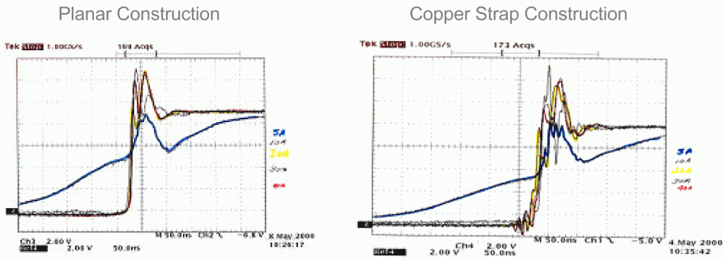
We investigated two forms of transformer construction:
• Flat planar construction of interleaved coils
• Copper straps over a single primary winding method
The following figure shows the effect of the transformer construction noise. These waveforms indicate that the flat planar construction is the least noisy choice. [1, 3, 8, 12]
 Figure 2. Output Voltage of Transformer Using Two Construction Methods
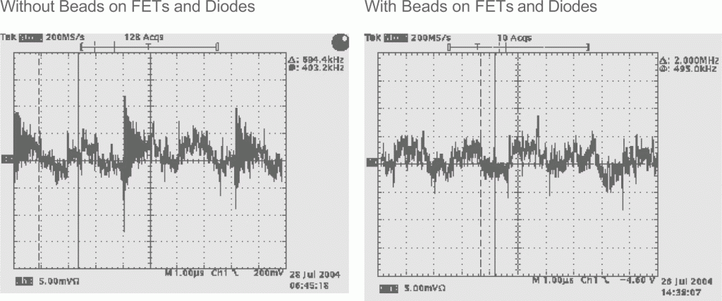
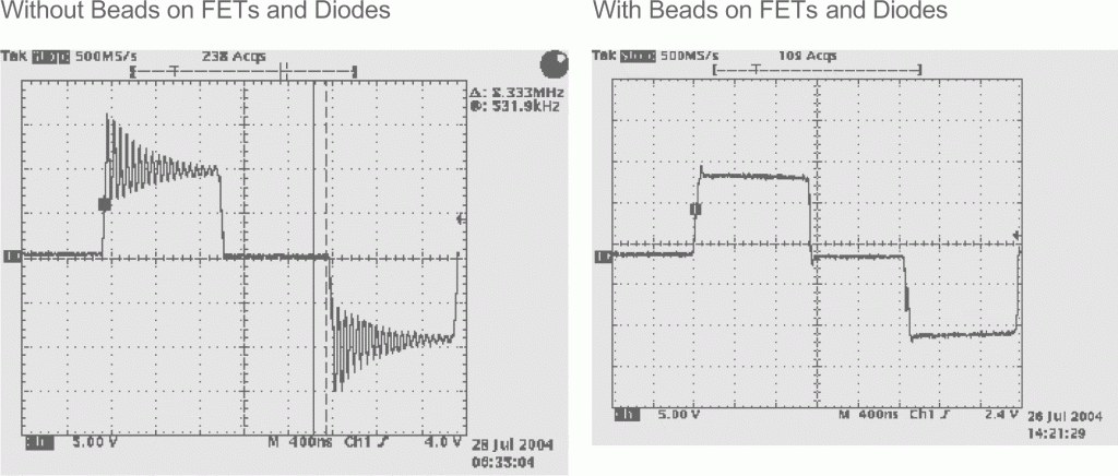
Using Amorphous Beads on Output Diodes and Ferrite Beads on FETs
We also examined how using amorphous beads on the output diode leads and ferrite beads on the FET leads affects parasitic ringing. To observe these effects, we took measurements at the output diode and the power supply’s output voltage. [6, 12, 13]
Figure 3 shows how using beads can effectively eliminate parasitic ringing at the output diode.
Figure 3. Parasitic Ringing at Output Diode
Figure 4 shows how using beads reduces parasitic ringing at the switching power supply’s output voltage. Note that the AC waveforms shown in these figures do not reflect all the noise elements, but they help illustrate the differential noise of the output and its frequency content.

Figure 4. AC Waveform of Parasitic Ringing on Power Supply Output Voltage
Conclusion
The reduction of noise at the linear regulator output demonstrates that the switching power supply design met the performance requirements described in this paper.
The linear regulator output exceeded the 1 mV accuracy requirement, maintained noise levels of less than 1 mV, and achieved all of the dynamic response requirements. The only drawback of this design is that the output diodes now require cooling. However, by using all known methods to reduce switching power supply noise, ATE test system designers can now implement linear regulators that meet requirements that have not been achievable in previous power supply designs.


